Images
Introduction
The geometry has been colored using per-vertex colors so far, which is a rather limited approach. In this part of the tutorial we're going to implement texture mapping to make the geometry look more interesting. This will also allow us to load and draw basic 3D models in a future chapter.
Adding a texture to our application will involve the following steps:
- Create an image object backed by device memory
- Fill it with pixels from an image file
- Create an image sampler
- Add a combined image sampler descriptor to sample colors from the texture
We've already worked with image objects before, but those were automatically
created by the swap chain extension. This time we'll have to create one by
ourselves. Creating an image and filling it with data is similar to vertex
buffer creation. We'll start by creating a staging resource and filling it with
pixel data and then we copy this to the final image object that we'll use for
rendering. Although it is possible to create a staging image for this purpose,
Vulkan also allows you to copy pixels from a VkBuffer to an image and the API
for this is actually faster on some hardware.
We'll first create this buffer and fill it with pixel values, and then we'll
create an image to copy the pixels to. Creating an image is not very different
from creating buffers. It involves querying the memory requirements, allocating
device memory and binding it, just like we've seen before.
However, there is something extra that we'll have to take care of when working with images. Images can have different layouts that affect how the pixels are organized in memory. Due to the way graphics hardware works, simply storing the pixels row by row may not lead to the best performance, for example. When performing any operation on images, you must make sure that they have the layout that is optimal for use in that operation. We've actually already seen some of these layouts when we specified the render pass:
-
VK_IMAGE_LAYOUT_PRESENT_SRC_KHR: Optimal for presentation -
VK_IMAGE_LAYOUT_COLOR_ATTACHMENT_OPTIMAL: Optimal as attachment for writing colors from the fragment shader -
VK_IMAGE_LAYOUT_TRANSFER_SRC_OPTIMAL: Optimal as source in a transfer operation, likevkCmdCopyImageToBuffer -
VK_IMAGE_LAYOUT_TRANSFER_DST_OPTIMAL: Optimal as destination in a transfer operation, likevkCmdCopyBufferToImage -
VK_IMAGE_LAYOUT_SHADER_READ_ONLY_OPTIMAL: Optimal for sampling from a shader
One of the most common ways to transition the layout of an image is a pipeline
barrier. Pipeline barriers are primarily used for synchronizing access to
resources, like making sure that an image was written to before it is read, but
they can also be used to transition layouts. In this chapter we'll see how
pipeline barriers are used for this purpose. Barriers can additionally be used
to transfer queue family ownership when using VK_SHARING_MODE_EXCLUSIVE.
Image library
There are many libraries available for loading images, and you can even write
your own code to load simple formats like BMP and PPM. In this tutorial we'll be
using the stb_image library from the stb collection.
The advantage of it is that all of the code is in a single file, so it doesn't
require any tricky build configuration. Download stb_image.h and store it in a
convenient location, like the directory where you saved GLFW and GLM. Add the
location to your include path.
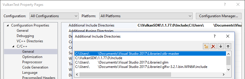
Visual Studio
Add the directory with stb_image.h in it to the Additional Include Directories paths.
Makefile
Add the directory with stb_image.h to the include directories for GCC:
VULKAN_SDK_PATH = /home/user/VulkanSDK/x.x.x.x/x86_64
STB_INCLUDE_PATH = /home/user/libraries/stb

...

CFLAGS = -std=c++17 -I$(VULKAN_SDK_PATH)/include -I$(STB_INCLUDE_PATH)
Loading an image
Include the image library like this:
#define STB_IMAGE_IMPLEMENTATION
#include <stb_image.h>
The header only defines the prototypes of the functions by default. One code
file needs to include the header with the STB_IMAGE_IMPLEMENTATION definition
to include the function bodies, otherwise we'll get linking errors.
void initVulkan() {
    ...
    createCommandPool();
    createTextureImage();
    createVertexBuffer();
    ...
}

...

void createTextureImage() {

}
Create a new function createTextureImage where we'll load an image and upload
it into a Vulkan image object. We're going to use command buffers, so it should
be called after createCommandPool.
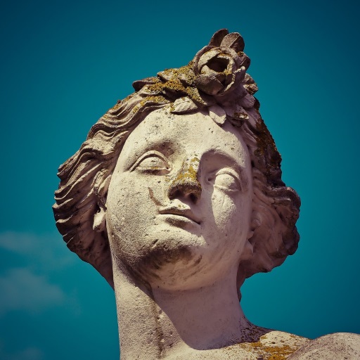
Create a new directory textures next to the shaders directory to store
texture images in. We're going to load an image called texture.jpg from that
directory. I've chosen to use the following
CC0 licensed image
resized to 512 x 512 pixels, but feel free to pick any image you want. The
library supports most common image file formats, like JPEG, PNG, BMP and GIF.
Loading an image with this library is really easy:
void createTextureImage() {
    int texWidth, texHeight, texChannels;
    stbi_uc* pixels = stbi_load("textures/texture.jpg", &texWidth, &texHeight, &texChannels, STBI_rgb_alpha);
    VkDeviceSize imageSize = texWidth * texHeight * 4;

    if (!pixels) {
        throw std::runtime_error("failed to load texture image!");
    }
}
The stbi_load function takes the file path and number of channels to load as
arguments. The STBI_rgb_alpha value forces the image to be loaded with an
alpha channel, even if it doesn't have one, which is nice for consistency with
other textures in the future. The middle three parameters are outputs for the
width, height and actual number of channels in the image. The pointer that is
returned is the first element in an array of pixel values. The pixels are laid
out row by row with 4 bytes per pixel in the case of STBI_rgb_alpha for a
total of texWidth * texHeight * 4 values.
Staging buffer
We're now going to create a buffer in host visible memory so that we can use
vkMapMemory and copy the pixels to it. Add variables for this temporary buffer
to the createTextureImage function:
VkBuffer stagingBuffer;
VkDeviceMemory stagingBufferMemory;
The buffer should be in host visible memory so that we can map it and it should be usable as a transfer source so that we can copy it to an image later on:
createBuffer(imageSize, VK_BUFFER_USAGE_TRANSFER_SRC_BIT, VK_MEMORY_PROPERTY_HOST_VISIBLE_BIT | VK_MEMORY_PROPERTY_HOST_COHERENT_BIT, stagingBuffer, stagingBufferMemory);
We can then directly copy the pixel values that we got from the image loading library to the buffer:
void* data;
vkMapMemory(device, stagingBufferMemory, 0, imageSize, 0, &data);
    memcpy(data, pixels, static_cast<size_t>(imageSize));
vkUnmapMemory(device, stagingBufferMemory);
Don't forget to clean up the original pixel array now:
stbi_image_free(pixels);
Texture Image
Although we could set up the shader to access the pixel values in the buffer, it's better to use image objects in Vulkan for this purpose. Image objects will make it easier and faster to retrieve colors by allowing us to use 2D coordinates, for one. Pixels within an image object are known as texels and we'll use that name from this point on. Add the following new class members:
VkImage textureImage;
VkDeviceMemory textureImageMemory;
The parameters for an image are specified in a VkImageCreateInfo struct:
VkImageCreateInfo imageInfo{};
imageInfo.sType = VK_STRUCTURE_TYPE_IMAGE_CREATE_INFO;
imageInfo.imageType = VK_IMAGE_TYPE_2D;
imageInfo.extent.width = static_cast<uint32_t>(texWidth);
imageInfo.extent.height = static_cast<uint32_t>(texHeight);
imageInfo.extent.depth = 1;
imageInfo.mipLevels = 1;
imageInfo.arrayLayers = 1;
The image type, specified in the imageType field, tells Vulkan with what kind
of coordinate system the texels in the image are going to be addressed. It is
possible to create 1D, 2D and 3D images. One dimensional images can be used to
store an array of data or gradient, two dimensional images are mainly used for
textures, and three dimensional images can be used to store voxel volumes, for
example. The extent field specifies the dimensions of the image, basically how
many texels there are on each axis. That's why depth must be 1 instead of
0. Our texture will not be an array and we won't be using mipmapping for now.
imageInfo.format = VK_FORMAT_R8G8B8A8_SRGB;
Vulkan supports many possible image formats, but we should use the same format for the texels as the pixels in the buffer, otherwise the copy operation will fail.
imageInfo.tiling = VK_IMAGE_TILING_OPTIMAL;
The tiling field can have one of two values:
-
VK_IMAGE_TILING_LINEAR: Texels are laid out in row-major order like ourpixelsarray -
VK_IMAGE_TILING_OPTIMAL: Texels are laid out in an implementation defined order for optimal access
Unlike the layout of an image, the tiling mode cannot be changed at a later
time. If you want to be able to directly access texels in the memory of the
image, then you must use VK_IMAGE_TILING_LINEAR. We will be using a staging
buffer instead of a staging image, so this won't be necessary. We will be using
VK_IMAGE_TILING_OPTIMAL for efficient access from the shader.
imageInfo.initialLayout = VK_IMAGE_LAYOUT_UNDEFINED;
There are only two possible values for the initialLayout of an image:
-
VK_IMAGE_LAYOUT_UNDEFINED: Not usable by the GPU and the very first transition will discard the texels. -
VK_IMAGE_LAYOUT_PREINITIALIZED: Not usable by the GPU, but the first transition will preserve the texels.
There are few situations where it is necessary for the texels to be preserved
during the first transition. One example, however, would be if you wanted to use
an image as a staging image in combination with the VK_IMAGE_TILING_LINEAR
layout. In that case, you'd want to upload the texel data to it and then
transition the image to be a transfer source without losing the data. In our
case, however, we're first going to transition the image to be a transfer
destination and then copy texel data to it from a buffer object, so we don't
need this property and can safely use VK_IMAGE_LAYOUT_UNDEFINED.
imageInfo.usage = VK_IMAGE_USAGE_TRANSFER_DST_BIT | VK_IMAGE_USAGE_SAMPLED_BIT;
The usage field has the same semantics as the one during buffer creation. The
image is going to be used as destination for the buffer copy, so it should be
set up as a transfer destination. We also want to be able to access the image
from the shader to color our mesh, so the usage should include
VK_IMAGE_USAGE_SAMPLED_BIT.
imageInfo.sharingMode = VK_SHARING_MODE_EXCLUSIVE;
The image will only be used by one queue family: the one that supports graphics (and therefore also) transfer operations.
imageInfo.samples = VK_SAMPLE_COUNT_1_BIT;
imageInfo.flags = 0; // Optional
The samples flag is related to multisampling. This is only relevant for images
that will be used as attachments, so stick to one sample. There are some
optional flags for images that are related to sparse images. Sparse images are
images where only certain regions are actually backed by memory. If you were
using a 3D texture for a voxel terrain, for example, then you could use this to
avoid allocating memory to store large volumes of "air" values. We won't be
using it in this tutorial, so leave it to its default value of 0.
if (vkCreateImage(device, &imageInfo, nullptr, &textureImage) != VK_SUCCESS) {
    throw std::runtime_error("failed to create image!");
}
The image is created using vkCreateImage, which doesn't have any particularly
noteworthy parameters. It is possible that the VK_FORMAT_R8G8B8A8_SRGB format
is not supported by the graphics hardware. You should have a list of acceptable
alternatives and go with the best one that is supported. However, support for
this particular format is so widespread that we'll skip this step. Using
different formats would also require annoying conversions. We will get back to
this in the depth buffer chapter, where we'll implement such a system.
VkMemoryRequirements memRequirements;
vkGetImageMemoryRequirements(device, textureImage, &memRequirements);

VkMemoryAllocateInfo allocInfo{};
allocInfo.sType = VK_STRUCTURE_TYPE_MEMORY_ALLOCATE_INFO;
allocInfo.allocationSize = memRequirements.size;
allocInfo.memoryTypeIndex = findMemoryType(memRequirements.memoryTypeBits, VK_MEMORY_PROPERTY_DEVICE_LOCAL_BIT);

if (vkAllocateMemory(device, &allocInfo, nullptr, &textureImageMemory) != VK_SUCCESS) {
    throw std::runtime_error("failed to allocate image memory!");
}

vkBindImageMemory(device, textureImage, textureImageMemory, 0);
Allocating memory for an image works in exactly the same way as allocating
memory for a buffer. Use vkGetImageMemoryRequirements instead of
vkGetBufferMemoryRequirements, and use vkBindImageMemory instead of
vkBindBufferMemory.
This function is already getting quite large and there'll be a need to create
more images in later chapters, so we should abstract image creation into a
createImage function, like we did for buffers. Create the function and move
the image object creation and memory allocation to it:
void createImage(uint32_t width, uint32_t height, VkFormat format, VkImageTiling tiling, VkImageUsageFlags usage, VkMemoryPropertyFlags properties, VkImage& image, VkDeviceMemory& imageMemory) {
    VkImageCreateInfo imageInfo{};
    imageInfo.sType = VK_STRUCTURE_TYPE_IMAGE_CREATE_INFO;
    imageInfo.imageType = VK_IMAGE_TYPE_2D;
    imageInfo.extent.width = width;
    imageInfo.extent.height = height;
    imageInfo.extent.depth = 1;
    imageInfo.mipLevels = 1;
    imageInfo.arrayLayers = 1;
    imageInfo.format = format;
    imageInfo.tiling = tiling;
    imageInfo.initialLayout = VK_IMAGE_LAYOUT_UNDEFINED;
    imageInfo.usage = usage;
    imageInfo.samples = VK_SAMPLE_COUNT_1_BIT;
    imageInfo.sharingMode = VK_SHARING_MODE_EXCLUSIVE;

    if (vkCreateImage(device, &imageInfo, nullptr, &image) != VK_SUCCESS) {
        throw std::runtime_error("failed to create image!");
    }

    VkMemoryRequirements memRequirements;
    vkGetImageMemoryRequirements(device, image, &memRequirements);

    VkMemoryAllocateInfo allocInfo{};
    allocInfo.sType = VK_STRUCTURE_TYPE_MEMORY_ALLOCATE_INFO;
    allocInfo.allocationSize = memRequirements.size;
    allocInfo.memoryTypeIndex = findMemoryType(memRequirements.memoryTypeBits, properties);

    if (vkAllocateMemory(device, &allocInfo, nullptr, &imageMemory) != VK_SUCCESS) {
        throw std::runtime_error("failed to allocate image memory!");
    }

    vkBindImageMemory(device, image, imageMemory, 0);
}
I've made the width, height, format, tiling mode, usage, and memory properties parameters, because these will all vary between the images we'll be creating throughout this tutorial.
The createTextureImage function can now be simplified to:
void createTextureImage() {
    int texWidth, texHeight, texChannels;
    stbi_uc* pixels = stbi_load("textures/texture.jpg", &texWidth, &texHeight, &texChannels, STBI_rgb_alpha);
    VkDeviceSize imageSize = texWidth * texHeight * 4;

    if (!pixels) {
        throw std::runtime_error("failed to load texture image!");
    }

    VkBuffer stagingBuffer;
    VkDeviceMemory stagingBufferMemory;
    createBuffer(imageSize, VK_BUFFER_USAGE_TRANSFER_SRC_BIT, VK_MEMORY_PROPERTY_HOST_VISIBLE_BIT | VK_MEMORY_PROPERTY_HOST_COHERENT_BIT, stagingBuffer, stagingBufferMemory);

    void* data;
    vkMapMemory(device, stagingBufferMemory, 0, imageSize, 0, &data);
        memcpy(data, pixels, static_cast<size_t>(imageSize));
    vkUnmapMemory(device, stagingBufferMemory);

    stbi_image_free(pixels);

    createImage(texWidth, texHeight, VK_FORMAT_R8G8B8A8_SRGB, VK_IMAGE_TILING_OPTIMAL, VK_IMAGE_USAGE_TRANSFER_DST_BIT | VK_IMAGE_USAGE_SAMPLED_BIT, VK_MEMORY_PROPERTY_DEVICE_LOCAL_BIT, textureImage, textureImageMemory);
}
Layout transitions
The function we're going to write now involves recording and executing a command buffer again, so now's a good time to move that logic into a helper function or two:
VkCommandBuffer beginSingleTimeCommands() {
    VkCommandBufferAllocateInfo allocInfo{};
    allocInfo.sType = VK_STRUCTURE_TYPE_COMMAND_BUFFER_ALLOCATE_INFO;
    allocInfo.level = VK_COMMAND_BUFFER_LEVEL_PRIMARY;
    allocInfo.commandPool = commandPool;
    allocInfo.commandBufferCount = 1;

    VkCommandBuffer commandBuffer;
    vkAllocateCommandBuffers(device, &allocInfo, &commandBuffer);

    VkCommandBufferBeginInfo beginInfo{};
    beginInfo.sType = VK_STRUCTURE_TYPE_COMMAND_BUFFER_BEGIN_INFO;
    beginInfo.flags = VK_COMMAND_BUFFER_USAGE_ONE_TIME_SUBMIT_BIT;

    vkBeginCommandBuffer(commandBuffer, &beginInfo);

    return commandBuffer;
}

void endSingleTimeCommands(VkCommandBuffer commandBuffer) {
    vkEndCommandBuffer(commandBuffer);

    VkSubmitInfo submitInfo{};
    submitInfo.sType = VK_STRUCTURE_TYPE_SUBMIT_INFO;
    submitInfo.commandBufferCount = 1;
    submitInfo.pCommandBuffers = &commandBuffer;

    vkQueueSubmit(graphicsQueue, 1, &submitInfo, VK_NULL_HANDLE);
    vkQueueWaitIdle(graphicsQueue);

    vkFreeCommandBuffers(device, commandPool, 1, &commandBuffer);
}
The code for these functions is based on the existing code in copyBuffer. You
can now simplify that function to:
void copyBuffer(VkBuffer srcBuffer, VkBuffer dstBuffer, VkDeviceSize size) {
VkCommandBuffer commandBuffer = beginSingleTimeCommands();
VkBufferCopy copyRegion{};
copyRegion.size = size;
vkCmdCopyBuffer(commandBuffer, srcBuffer, dstBuffer, 1, ©Region);
endSingleTimeCommands(commandBuffer);
}
If we were still using buffers, then we could now write a function to record and
execute vkCmdCopyBufferToImage to finish the job, but this command requires
the image to be in the right layout first. Create a new function to handle
layout transitions:
void transitionImageLayout(VkImage image, VkFormat format, VkImageLayout oldLayout, VkImageLayout newLayout) {
    VkCommandBuffer commandBuffer = beginSingleTimeCommands();

    endSingleTimeCommands(commandBuffer);
}
One of the most common ways to perform layout transitions is using an image
memory barrier. A pipeline barrier like that is generally used to synchronize
access to resources, like ensuring that a write to a buffer completes before
reading from it, but it can also be used to transition image layouts and
transfer queue family ownership when VK_SHARING_MODE_EXCLUSIVE is used. There
is an equivalent buffer memory barrier to do this for buffers.
VkImageMemoryBarrier barrier{};
barrier.sType = VK_STRUCTURE_TYPE_IMAGE_MEMORY_BARRIER;
barrier.oldLayout = oldLayout;
barrier.newLayout = newLayout;
The first two fields specify layout transition. It is possible to use
VK_IMAGE_LAYOUT_UNDEFINED as oldLayout if you don't care about the existing
contents of the image.
barrier.srcQueueFamilyIndex = VK_QUEUE_FAMILY_IGNORED;
barrier.dstQueueFamilyIndex = VK_QUEUE_FAMILY_IGNORED;
If you are using the barrier to transfer queue family ownership, then these two
fields should be the indices of the queue families. They must be set to
VK_QUEUE_FAMILY_IGNORED if you don't want to do this (not the default value!).
barrier.image = image;
barrier.subresourceRange.aspectMask = VK_IMAGE_ASPECT_COLOR_BIT;
barrier.subresourceRange.baseMipLevel = 0;
barrier.subresourceRange.levelCount = 1;
barrier.subresourceRange.baseArrayLayer = 0;
barrier.subresourceRange.layerCount = 1;
The image and subresourceRange specify the image that is affected and the
specific part of the image. Our image is not an array and does not have mipmapping
levels, so only one level and layer are specified.
barrier.srcAccessMask = 0; // TODO
barrier.dstAccessMask = 0; // TODO
Barriers are primarily used for synchronization purposes, so you must specify
which types of operations that involve the resource must happen before the
barrier, and which operations that involve the resource must wait on the
barrier. We need to do that despite already using vkQueueWaitIdle to manually
synchronize. The right values depend on the old and new layout, so we'll get
back to this once we've figured out which transitions we're going to use.
vkCmdPipelineBarrier(
    commandBuffer,
    0 /* TODO */, 0 /* TODO */,
    0,
    0, nullptr,
    0, nullptr,
    1, &barrier
);
All types of pipeline barriers are submitted using the same function. The first
parameter after the command buffer specifies in which pipeline stage the
operations occur that should happen before the barrier. The second parameter
specifies the pipeline stage in which operations will wait on the barrier. The
pipeline stages that you are allowed to specify before and after the barrier
depend on how you use the resource before and after the barrier. The allowed
values are listed in this table
of the specification. For example, if you're going to read from a uniform after
the barrier, you would specify a usage of VK_ACCESS_UNIFORM_READ_BIT and the
earliest shader that will read from the uniform as pipeline stage, for example
VK_PIPELINE_STAGE_FRAGMENT_SHADER_BIT. It would not make sense to specify
a non-shader pipeline stage for this type of usage and the validation layers
will warn you when you specify a pipeline stage that does not match the type of
usage.
The third parameter is either 0 or VK_DEPENDENCY_BY_REGION_BIT. The latter
turns the barrier into a per-region condition. That means that the
implementation is allowed to already begin reading from the parts of a resource
that were written so far, for example.
The last three pairs of parameters reference arrays of pipeline barriers of the
three available types: memory barriers, buffer memory barriers, and image memory
barriers like the one we're using here. Note that we're not using the VkFormat
parameter yet, but we'll be using that one for special transitions in the depth
buffer chapter.
Copying buffer to image
Before we get back to createTextureImage, we're going to write one more helper
function: copyBufferToImage:
void copyBufferToImage(VkBuffer buffer, VkImage image, uint32_t width, uint32_t height) {
    VkCommandBuffer commandBuffer = beginSingleTimeCommands();

    endSingleTimeCommands(commandBuffer);
}
Just like with buffer copies, you need to specify which part of the buffer is
going to be copied to which part of the image. This happens through
VkBufferImageCopy structs:
VkBufferImageCopy region{};
region.bufferOffset = 0;
region.bufferRowLength = 0;
region.bufferImageHeight = 0;

region.imageSubresource.aspectMask = VK_IMAGE_ASPECT_COLOR_BIT;
region.imageSubresource.mipLevel = 0;
region.imageSubresource.baseArrayLayer = 0;
region.imageSubresource.layerCount = 1;

region.imageOffset = {0, 0, 0};
region.imageExtent = {
    width,
    height,
    1
};
Most of these fields are self-explanatory. The bufferOffset specifies the byte
offset in the buffer at which the pixel values start. The bufferRowLength and
bufferImageHeight fields specify how the pixels are laid out in memory. For
example, you could have some padding bytes between rows of the image. Specifying
0 for both indicates that the pixels are simply tightly packed like they are
in our case. The imageSubresource, imageOffset and imageExtent fields
indicate to which part of the image we want to copy the pixels.
Buffer to image copy operations are enqueued using the vkCmdCopyBufferToImage
function:
vkCmdCopyBufferToImage(
commandBuffer,
buffer,
image,
VK_IMAGE_LAYOUT_TRANSFER_DST_OPTIMAL,
1,
®ion
);
The fourth parameter indicates which layout the image is currently using. I'm
assuming here that the image has already been transitioned to the layout that is
optimal for copying pixels to. Right now we're only copying one chunk of pixels
to the whole image, but it's possible to specify an array of VkBufferImageCopy
to perform many different copies from this buffer to the image in one operation.
Preparing the texture image
We now have all of the tools we need to finish setting up the texture image, so
we're going back to the createTextureImage function. The last thing we did
there was creating the texture image. The next step is to copy the staging
buffer to the texture image. This involves two steps:
- Transition the texture image to
VK_IMAGE_LAYOUT_TRANSFER_DST_OPTIMAL - Execute the buffer to image copy operation
This is easy to do with the functions we just created:
transitionImageLayout(textureImage, VK_FORMAT_R8G8B8A8_SRGB, VK_IMAGE_LAYOUT_UNDEFINED, VK_IMAGE_LAYOUT_TRANSFER_DST_OPTIMAL);
copyBufferToImage(stagingBuffer, textureImage, static_cast<uint32_t>(texWidth), static_cast<uint32_t>(texHeight));
The image was created with the VK_IMAGE_LAYOUT_UNDEFINED layout, so that one
should be specified as old layout when transitioning textureImage. Remember
that we can do this because we don't care about its contents before performing
the copy operation.
To be able to start sampling from the texture image in the shader, we need one last transition to prepare it for shader access:
transitionImageLayout(textureImage, VK_FORMAT_R8G8B8A8_SRGB, VK_IMAGE_LAYOUT_TRANSFER_DST_OPTIMAL, VK_IMAGE_LAYOUT_SHADER_READ_ONLY_OPTIMAL);
Transition barrier masks
If you run your application with validation layers enabled now, then you'll see that
it complains about the access masks and pipeline stages in
transitionImageLayout being invalid. We still need to set those based on the
layouts in the transition.
There are two transitions we need to handle:
- Undefined → transfer destination: transfer writes that don't need to wait on anything
- Transfer destination → shader reading: shader reads should wait on transfer writes, specifically the shader reads in the fragment shader, because that's where we're going to use the texture
These rules are specified using the following access masks and pipeline stages:
VkPipelineStageFlags sourceStage;
VkPipelineStageFlags destinationStage;

if (oldLayout == VK_IMAGE_LAYOUT_UNDEFINED && newLayout == VK_IMAGE_LAYOUT_TRANSFER_DST_OPTIMAL) {
    barrier.srcAccessMask = 0;
    barrier.dstAccessMask = VK_ACCESS_TRANSFER_WRITE_BIT;

    sourceStage = VK_PIPELINE_STAGE_TOP_OF_PIPE_BIT;
    destinationStage = VK_PIPELINE_STAGE_TRANSFER_BIT;
} else if (oldLayout == VK_IMAGE_LAYOUT_TRANSFER_DST_OPTIMAL && newLayout == VK_IMAGE_LAYOUT_SHADER_READ_ONLY_OPTIMAL) {
    barrier.srcAccessMask = VK_ACCESS_TRANSFER_WRITE_BIT;
    barrier.dstAccessMask = VK_ACCESS_SHADER_READ_BIT;

    sourceStage = VK_PIPELINE_STAGE_TRANSFER_BIT;
    destinationStage = VK_PIPELINE_STAGE_FRAGMENT_SHADER_BIT;
} else {
    throw std::invalid_argument("unsupported layout transition!");
}

vkCmdPipelineBarrier(
    commandBuffer,
    sourceStage, destinationStage,
    0,
    0, nullptr,
    0, nullptr,
    1, &barrier
);
As you can see in the aforementioned table, transfer writes must occur in the
pipeline transfer stage. Since the writes don't have to wait on anything, you
may specify an empty access mask and the earliest possible pipeline stage
VK_PIPELINE_STAGE_TOP_OF_PIPE_BIT for the pre-barrier operations. It should be
noted that VK_PIPELINE_STAGE_TRANSFER_BIT is not a real stage within the
graphics and compute pipelines. It is more of a pseudo-stage where transfers
happen. See the documentation
for more information and other examples of pseudo-stages.
The image will be written in the same pipeline stage and subsequently read by the fragment shader, which is why we specify shader reading access in the fragment shader pipeline stage.
If we need to do more transitions in the future, then we'll extend the function. The application should now run successfully, although there are of course no visual changes yet.
One thing to note is that command buffer submission results in implicit
VK_ACCESS_HOST_WRITE_BIT synchronization at the beginning. Since the
transitionImageLayout function executes a command buffer with only a single
command, you could use this implicit synchronization and set srcAccessMask to
0 if you ever needed a VK_ACCESS_HOST_WRITE_BIT dependency in a layout
transition. It's up to you if you want to be explicit about it or not, but I'm
personally not a fan of relying on these OpenGL-like "hidden" operations.
There is actually a special type of image layout that supports all operations,
VK_IMAGE_LAYOUT_GENERAL. The problem with it, of course, is that it doesn't
necessarily offer the best performance for any operation. It is required for
some special cases, like using an image as both input and output, or for reading
an image after it has left the preinitialized layout.
All of the helper functions that submit commands so far have been set up to
execute synchronously by waiting for the queue to become idle. For practical
applications it is recommended to combine these operations in a single command
buffer and execute them asynchronously for higher throughput, especially the
transitions and copy in the createTextureImage function. Try to experiment
with this by creating a setupCommandBuffer that the helper functions record
commands into, and add a flushSetupCommands to execute the commands that have
been recorded so far. It's best to do this after the texture mapping works to
check if the texture resources are still set up correctly.
Cleanup
Finish the createTextureImage function by cleaning up the staging buffer and
its memory at the end:
    transitionImageLayout(textureImage, VK_FORMAT_R8G8B8A8_SRGB, VK_IMAGE_LAYOUT_TRANSFER_DST_OPTIMAL, VK_IMAGE_LAYOUT_SHADER_READ_ONLY_OPTIMAL);

    vkDestroyBuffer(device, stagingBuffer, nullptr);
    vkFreeMemory(device, stagingBufferMemory, nullptr);
}
The main texture image is used until the end of the program:
void cleanup() {
    cleanupSwapChain();

    vkDestroyImage(device, textureImage, nullptr);
    vkFreeMemory(device, textureImageMemory, nullptr);

    ...
}
The image now contains the texture, but we still need a way to access it from the graphics pipeline. We'll work on that in the next chapter.