Combined image sampler
Introduction
We looked at descriptors for the first time in the uniform buffers part of the tutorial. In this chapter we will look at a new type of descriptor: combined image sampler. This descriptor makes it possible for shaders to access an image resource through a sampler object like the one we created in the previous chapter.
We'll start by modifying the descriptor set layout, descriptor pool and descriptor
set to include such a combined image sampler descriptor. After that, we're going
to add texture coordinates to Vertex and modify the fragment shader to read
colors from the texture instead of just interpolating the vertex colors.
Updating the descriptors
Browse to the createDescriptorSetLayout function and add a
VkDescriptorSetLayoutBinding for a combined image sampler descriptor. We'll
simply put it in the binding after the uniform buffer:
VkDescriptorSetLayoutBinding samplerLayoutBinding{};
samplerLayoutBinding.binding = 1;
samplerLayoutBinding.descriptorCount = 1;
samplerLayoutBinding.descriptorType = VK_DESCRIPTOR_TYPE_COMBINED_IMAGE_SAMPLER;
samplerLayoutBinding.pImmutableSamplers = nullptr;
samplerLayoutBinding.stageFlags = VK_SHADER_STAGE_FRAGMENT_BIT;

std::array<VkDescriptorSetLayoutBinding, 2> bindings = {uboLayoutBinding, samplerLayoutBinding};
VkDescriptorSetLayoutCreateInfo layoutInfo{};
layoutInfo.sType = VK_STRUCTURE_TYPE_DESCRIPTOR_SET_LAYOUT_CREATE_INFO;
layoutInfo.bindingCount = static_cast<uint32_t>(bindings.size());
layoutInfo.pBindings = bindings.data();
Make sure to set the stageFlags to indicate that we intend to use the combined
image sampler descriptor in the fragment shader. That's where the color of the
fragment is going to be determined. It is possible to use texture sampling in
the vertex shader, for example to dynamically deform a grid of vertices by a
heightmap.
We must also create a larger descriptor pool to make room for the allocation
of the combined image sampler by adding another VkPoolSize of type
VK_DESCRIPTOR_TYPE_COMBINED_IMAGE_SAMPLER to the
VkDescriptorPoolCreateInfo. Go to the createDescriptorPool function and
modify it to include a VkDescriptorPoolSize for this descriptor:
std::array<VkDescriptorPoolSize, 2> poolSizes{};
poolSizes[0].type = VK_DESCRIPTOR_TYPE_UNIFORM_BUFFER;
poolSizes[0].descriptorCount = static_cast<uint32_t>(MAX_FRAMES_IN_FLIGHT);
poolSizes[1].type = VK_DESCRIPTOR_TYPE_COMBINED_IMAGE_SAMPLER;
poolSizes[1].descriptorCount = static_cast<uint32_t>(MAX_FRAMES_IN_FLIGHT);

VkDescriptorPoolCreateInfo poolInfo{};
poolInfo.sType = VK_STRUCTURE_TYPE_DESCRIPTOR_POOL_CREATE_INFO;
poolInfo.poolSizeCount = static_cast<uint32_t>(poolSizes.size());
poolInfo.pPoolSizes = poolSizes.data();
poolInfo.maxSets = static_cast<uint32_t>(MAX_FRAMES_IN_FLIGHT);
Inadequate descriptor pools are a good example of a problem that the validation
layers will not catch: As of Vulkan 1.1, vkAllocateDescriptorSets may fail
with the error code VK_ERROR_POOL_OUT_OF_MEMORY if the pool is not
sufficiently large, but the driver may also try to solve the problem internally.
This means that sometimes (depending on hardware, pool size and allocation size)
the driver will let us get away with an allocation that exceeds the limits of
our descriptor pool. Other times, vkAllocateDescriptorSets will fail and
return VK_ERROR_POOL_OUT_OF_MEMORY. This can be particularly frustrating if
the allocation succeeds on some machines, but fails on others.
Since Vulkan shifts the responsiblity for the allocation to the driver, it is no
longer a strict requirement to only allocate as many descriptors of a certain
type (VK_DESCRIPTOR_TYPE_COMBINED_IMAGE_SAMPLER, etc.) as specified by the
corresponding descriptorCount members for the creation of the descriptor pool.
However, it remains best practise to do so, and in the future,
VK_LAYER_KHRONOS_validation will warn about this type of problem if you enable
Best Practice Validation.
The final step is to bind the actual image and sampler resources to the
descriptors in the descriptor set. Go to the createDescriptorSets function.
for (size_t i = 0; i < MAX_FRAMES_IN_FLIGHT; i++) {
    VkDescriptorBufferInfo bufferInfo{};
    bufferInfo.buffer = uniformBuffers[i];
    bufferInfo.offset = 0;
    bufferInfo.range = sizeof(UniformBufferObject);

    VkDescriptorImageInfo imageInfo{};
    imageInfo.imageLayout = VK_IMAGE_LAYOUT_SHADER_READ_ONLY_OPTIMAL;
    imageInfo.imageView = textureImageView;
    imageInfo.sampler = textureSampler;

    ...
}
The resources for a combined image sampler structure must be specified in a
VkDescriptorImageInfo struct, just like the buffer resource for a uniform
buffer descriptor is specified in a VkDescriptorBufferInfo struct. This is
where the objects from the previous chapter come together.
std::array<VkWriteDescriptorSet, 2> descriptorWrites{};

descriptorWrites[0].sType = VK_STRUCTURE_TYPE_WRITE_DESCRIPTOR_SET;
descriptorWrites[0].dstSet = descriptorSets[i];
descriptorWrites[0].dstBinding = 0;
descriptorWrites[0].dstArrayElement = 0;
descriptorWrites[0].descriptorType = VK_DESCRIPTOR_TYPE_UNIFORM_BUFFER;
descriptorWrites[0].descriptorCount = 1;
descriptorWrites[0].pBufferInfo = &bufferInfo;

descriptorWrites[1].sType = VK_STRUCTURE_TYPE_WRITE_DESCRIPTOR_SET;
descriptorWrites[1].dstSet = descriptorSets[i];
descriptorWrites[1].dstBinding = 1;
descriptorWrites[1].dstArrayElement = 0;
descriptorWrites[1].descriptorType = VK_DESCRIPTOR_TYPE_COMBINED_IMAGE_SAMPLER;
descriptorWrites[1].descriptorCount = 1;
descriptorWrites[1].pImageInfo = &imageInfo;

vkUpdateDescriptorSets(device, static_cast<uint32_t>(descriptorWrites.size()), descriptorWrites.data(), 0, nullptr);
The descriptors must be updated with this image info, just like the buffer. This
time we're using the pImageInfo array instead of pBufferInfo. The descriptors
are now ready to be used by the shaders!
Texture coordinates
There is one important ingredient for texture mapping that is still missing, and that's the actual texture coordinates for each vertex. The texture coordinates determine how the image is actually mapped to the geometry.
struct Vertex {
    glm::vec2 pos;
    glm::vec3 color;
    glm::vec2 texCoord;

    static VkVertexInputBindingDescription getBindingDescription() {
        VkVertexInputBindingDescription bindingDescription{};
        bindingDescription.binding = 0;
        bindingDescription.stride = sizeof(Vertex);
        bindingDescription.inputRate = VK_VERTEX_INPUT_RATE_VERTEX;

        return bindingDescription;
    }

    static std::array<VkVertexInputAttributeDescription, 3> getAttributeDescriptions() {
        std::array<VkVertexInputAttributeDescription, 3> attributeDescriptions{};

        attributeDescriptions[0].binding = 0;
        attributeDescriptions[0].location = 0;
        attributeDescriptions[0].format = VK_FORMAT_R32G32_SFLOAT;
        attributeDescriptions[0].offset = offsetof(Vertex, pos);

        attributeDescriptions[1].binding = 0;
        attributeDescriptions[1].location = 1;
        attributeDescriptions[1].format = VK_FORMAT_R32G32B32_SFLOAT;
        attributeDescriptions[1].offset = offsetof(Vertex, color);

        attributeDescriptions[2].binding = 0;
        attributeDescriptions[2].location = 2;
        attributeDescriptions[2].format = VK_FORMAT_R32G32_SFLOAT;
        attributeDescriptions[2].offset = offsetof(Vertex, texCoord);

        return attributeDescriptions;
    }
};
Modify the Vertex struct to include a vec2 for texture coordinates. Make
sure to also add a VkVertexInputAttributeDescription so that we can use access
texture coordinates as input in the vertex shader. That is necessary to be able
to pass them to the fragment shader for interpolation across the surface of the
square.
const std::vector<Vertex> vertices = {
    {{-0.5f, -0.5f}, {1.0f, 0.0f, 0.0f}, {1.0f, 0.0f}},
    {{0.5f, -0.5f}, {0.0f, 1.0f, 0.0f}, {0.0f, 0.0f}},
    {{0.5f, 0.5f}, {0.0f, 0.0f, 1.0f}, {0.0f, 1.0f}},
    {{-0.5f, 0.5f}, {1.0f, 1.0f, 1.0f}, {1.0f, 1.0f}}
};
In this tutorial, I will simply fill the square with the texture by using
coordinates from 0, 0 in the top-left corner to 1, 1 in the bottom-right
corner. Feel free to experiment with different coordinates. Try using
coordinates below 0 or above 1 to see the addressing modes in action!
Shaders
The final step is modifying the shaders to sample colors from the texture. We first need to modify the vertex shader to pass through the texture coordinates to the fragment shader:
layout(location = 0) in vec2 inPosition;
layout(location = 1) in vec3 inColor;
layout(location = 2) in vec2 inTexCoord;

layout(location = 0) out vec3 fragColor;
layout(location = 1) out vec2 fragTexCoord;

void main() {
    gl_Position = ubo.proj * ubo.view * ubo.model * vec4(inPosition, 0.0, 1.0);
    fragColor = inColor;
    fragTexCoord = inTexCoord;
}
Just like the per vertex colors, the fragTexCoord values will be smoothly
interpolated across the area of the square by the rasterizer. We can visualize
this by having the fragment shader output the texture coordinates as colors:
#version 450

layout(location = 0) in vec3 fragColor;
layout(location = 1) in vec2 fragTexCoord;

layout(location = 0) out vec4 outColor;

void main() {
    outColor = vec4(fragTexCoord, 0.0, 1.0);
}
You should see something like the image below. Don't forget to recompile the shaders!
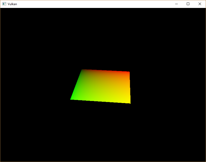
The green channel represents the horizontal coordinates and the red channel the
vertical coordinates. The black and yellow corners confirm that the texture
coordinates are correctly interpolated from 0, 0 to 1, 1 across the square.
Visualizing data using colors is the shader programming equivalent of printf
debugging, for lack of a better option!
A combined image sampler descriptor is represented in GLSL by a sampler uniform. Add a reference to it in the fragment shader:
layout(binding = 1) uniform sampler2D texSampler;
There are equivalent sampler1D and sampler3D types for other types of
images. Make sure to use the correct binding here.
void main() {
    outColor = texture(texSampler, fragTexCoord);
}
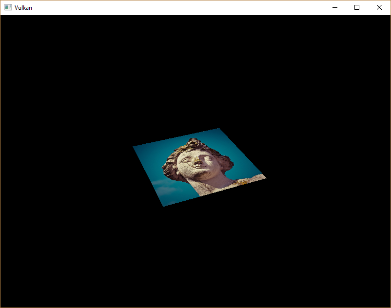
Textures are sampled using the built-in texture function. It takes a sampler
and coordinate as arguments. The sampler automatically takes care of the
filtering and transformations in the background. You should now see the texture
on the square when you run the application:
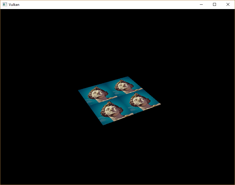
Try experimenting with the addressing modes by scaling the texture coordinates
to values higher than 1. For example, the following fragment shader produces
the result in the image below when using VK_SAMPLER_ADDRESS_MODE_REPEAT:
void main() {
    outColor = texture(texSampler, fragTexCoord * 2.0);
}
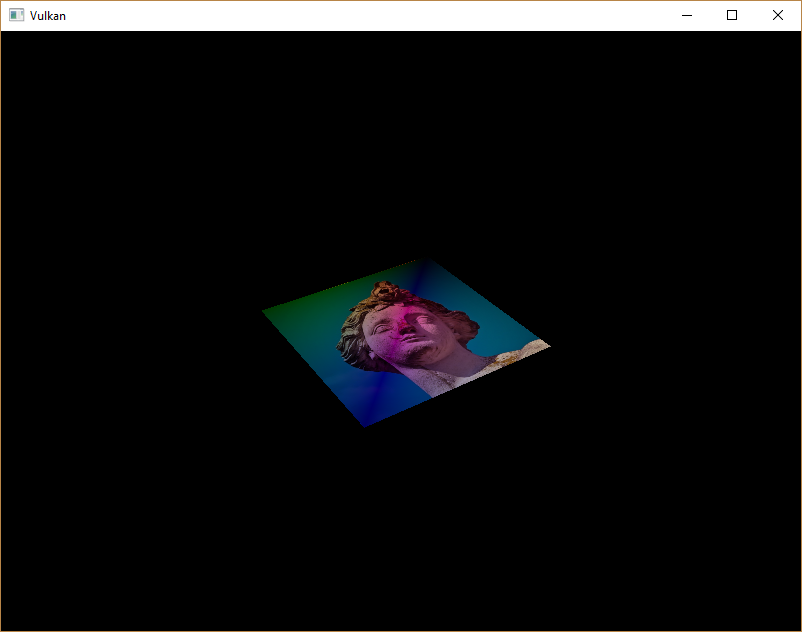
You can also manipulate the texture colors using the vertex colors:
void main() {
    outColor = vec4(fragColor * texture(texSampler, fragTexCoord).rgb, 1.0);
}
I've separated the RGB and alpha channels here to not scale the alpha channel.
You now know how to access images in shaders! This is a very powerful technique when combined with images that are also written to in framebuffers. You can use these images as inputs to implement cool effects like post-processing and camera displays within the 3D world.