Fixed functions
The older graphics APIs provided default state for most of the stages of the graphics pipeline. In Vulkan you have to be explicit about most pipeline states as it'll be baked into an immutable pipeline state object. In this chapter we'll fill in all of the structures to configure these fixed-function operations.
Dynamic state
While most of the pipeline state needs to be baked into the pipeline state,
a limited amount of the state can actually be changed without recreating the
pipeline at draw time. Examples are the size of the viewport, line width
and blend constants. If you want to use dynamic state and keep these properties out,
then you'll have to fill in a VkPipelineDynamicStateCreateInfo structure like this:
std::vector<VkDynamicState> dynamicStates = {
    VK_DYNAMIC_STATE_VIEWPORT,
    VK_DYNAMIC_STATE_SCISSOR
};

VkPipelineDynamicStateCreateInfo dynamicState{};
dynamicState.sType = VK_STRUCTURE_TYPE_PIPELINE_DYNAMIC_STATE_CREATE_INFO;
dynamicState.dynamicStateCount = static_cast<uint32_t>(dynamicStates.size());
dynamicState.pDynamicStates = dynamicStates.data();
This will cause the configuration of these values to be ignored and you will be able (and required) to specify the data at drawing time. This results in a more flexible setup and is very common for things like viewport and scissor state, which would result in a more complex setup when being baked into the pipeline state.
Vertex input
The VkPipelineVertexInputStateCreateInfo structure describes the format of the
vertex data that will be passed to the vertex shader. It describes this in
roughly two ways:
- Bindings: spacing between data and whether the data is per-vertex or per-instance (see instancing)
- Attribute descriptions: type of the attributes passed to the vertex shader, which binding to load them from and at which offset
Because we're hard coding the vertex data directly in the vertex shader, we'll fill in this structure to specify that there is no vertex data to load for now. We'll get back to it in the vertex buffer chapter.
VkPipelineVertexInputStateCreateInfo vertexInputInfo{};
vertexInputInfo.sType = VK_STRUCTURE_TYPE_PIPELINE_VERTEX_INPUT_STATE_CREATE_INFO;
vertexInputInfo.vertexBindingDescriptionCount = 0;
vertexInputInfo.pVertexBindingDescriptions = nullptr; // Optional
vertexInputInfo.vertexAttributeDescriptionCount = 0;
vertexInputInfo.pVertexAttributeDescriptions = nullptr; // Optional
The pVertexBindingDescriptions and pVertexAttributeDescriptions members
point to an array of structs that describe the aforementioned details for
loading vertex data. Add this structure to the createGraphicsPipeline function
right after the shaderStages array.
Input assembly
The VkPipelineInputAssemblyStateCreateInfo struct describes two things: what
kind of geometry will be drawn from the vertices and if primitive restart should
be enabled. The former is specified in the topology member and can have values
like:
-
VK_PRIMITIVE_TOPOLOGY_POINT_LIST: points from vertices -
VK_PRIMITIVE_TOPOLOGY_LINE_LIST: line from every 2 vertices without reuse -
VK_PRIMITIVE_TOPOLOGY_LINE_STRIP: the end vertex of every line is used as start vertex for the next line -
VK_PRIMITIVE_TOPOLOGY_TRIANGLE_LIST: triangle from every 3 vertices without reuse -
VK_PRIMITIVE_TOPOLOGY_TRIANGLE_STRIP: the second and third vertex of every triangle are used as first two vertices of the next triangle
Normally, the vertices are loaded from the vertex buffer by index in sequential
order, but with an element buffer you can specify the indices to use yourself.
This allows you to perform optimizations like reusing vertices. If you set the
primitiveRestartEnable member to VK_TRUE, then it's possible to break up
lines and triangles in the _STRIP topology modes by using a special index of
0xFFFF or 0xFFFFFFFF.
We intend to draw triangles throughout this tutorial, so we'll stick to the following data for the structure:
VkPipelineInputAssemblyStateCreateInfo inputAssembly{};
inputAssembly.sType = VK_STRUCTURE_TYPE_PIPELINE_INPUT_ASSEMBLY_STATE_CREATE_INFO;
inputAssembly.topology = VK_PRIMITIVE_TOPOLOGY_TRIANGLE_LIST;
inputAssembly.primitiveRestartEnable = VK_FALSE;
Viewports and scissors
A viewport basically describes the region of the framebuffer that the output
will be rendered to. This will almost always be (0, 0) to (width, height)
and in this tutorial that will also be the case.
VkViewport viewport{};
viewport.x = 0.0f;
viewport.y = 0.0f;
viewport.width = (float) swapChainExtent.width;
viewport.height = (float) swapChainExtent.height;
viewport.minDepth = 0.0f;
viewport.maxDepth = 1.0f;
Remember that the size of the swap chain and its images may differ from the
WIDTH and HEIGHT of the window. The swap chain images will be used as
framebuffers later on, so we should stick to their size.
The minDepth and maxDepth values specify the range of depth values to use
for the framebuffer. These values must be within the [0.0f, 1.0f] range, but
minDepth may be higher than maxDepth. If you aren't doing anything special,
then you should stick to the standard values of 0.0f and 1.0f.
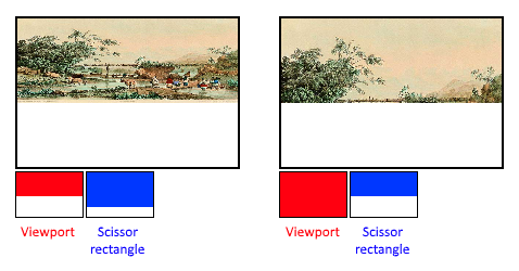
While viewports define the transformation from the image to the framebuffer, scissor rectangles define in which regions pixels will actually be stored. Any pixels outside the scissor rectangles will be discarded by the rasterizer. They function like a filter rather than a transformation. The difference is illustrated below. Note that the left scissor rectangle is just one of the many possibilities that would result in that image, as long as it's larger than the viewport.
So if we wanted to draw to the entire framebuffer, we would specify a scissor rectangle that covers it entirely:
VkRect2D scissor{};
scissor.offset = {0, 0};
scissor.extent = swapChainExtent;
Viewport(s) and scissor rectangle(s) can either be specified as a static part of the pipeline or as a dynamic state set in the command buffer. While the former is more in line with the other states it's often convenient to make viewport and scissor state dynamic as it gives you a lot more flexibility. This is very common and all implementations can handle this dynamic state without a performance penalty.
When opting for dynamic viewport(s) and scissor rectangle(s) you need to enable the respective dynamic states for the pipeline:
std::vector<VkDynamicState> dynamicStates = {
    VK_DYNAMIC_STATE_VIEWPORT,
    VK_DYNAMIC_STATE_SCISSOR
};

VkPipelineDynamicStateCreateInfo dynamicState{};
dynamicState.sType = VK_STRUCTURE_TYPE_PIPELINE_DYNAMIC_STATE_CREATE_INFO;
dynamicState.dynamicStateCount = static_cast<uint32_t>(dynamicStates.size());
dynamicState.pDynamicStates = dynamicStates.data();
And then you only need to specify their count at pipeline creation time:
VkPipelineViewportStateCreateInfo viewportState{};
viewportState.sType = VK_STRUCTURE_TYPE_PIPELINE_VIEWPORT_STATE_CREATE_INFO;
viewportState.viewportCount = 1;
viewportState.scissorCount = 1;
The actual viewport(s) and scissor rectangle(s) will then later be set up at drawing time.
With dynamic state it's even possible to specify different viewports and or scissor rectangles within a single command buffer.
Without dynamic state, the viewport and scissor rectangle need to be set in the pipeline using the VkPipelineViewportStateCreateInfo struct. This makes the viewport and scissor rectangle for this pipeline immutable.
Any changes required to these values would require a new pipeline to be created with the new values.
VkPipelineViewportStateCreateInfo viewportState{};
viewportState.sType = VK_STRUCTURE_TYPE_PIPELINE_VIEWPORT_STATE_CREATE_INFO;
viewportState.viewportCount = 1;
viewportState.pViewports = &viewport;
viewportState.scissorCount = 1;
viewportState.pScissors = &scissor;
Independent of how you set them, it's possible to use multiple viewports and scissor rectangles on some graphics cards, so the structure members reference an array of them. Using multiple requires enabling a GPU feature (see logical device creation).
Rasterizer
The rasterizer takes the geometry that is shaped by the vertices from the vertex
shader and turns it into fragments to be colored by the fragment shader. It also
performs depth testing,
face culling and the scissor
test, and it can be configured to output fragments that fill entire polygons or
just the edges (wireframe rendering). All this is configured using the
VkPipelineRasterizationStateCreateInfo structure.
VkPipelineRasterizationStateCreateInfo rasterizer{};
rasterizer.sType = VK_STRUCTURE_TYPE_PIPELINE_RASTERIZATION_STATE_CREATE_INFO;
rasterizer.depthClampEnable = VK_FALSE;
If depthClampEnable is set to VK_TRUE, then fragments that are beyond the
near and far planes are clamped to them as opposed to discarding them. This is
useful in some special cases like shadow maps. Using this requires enabling a
GPU feature.
rasterizer.rasterizerDiscardEnable = VK_FALSE;
If rasterizerDiscardEnable is set to VK_TRUE, then geometry never passes
through the rasterizer stage. This basically disables any output to the
framebuffer.
rasterizer.polygonMode = VK_POLYGON_MODE_FILL;
The polygonMode determines how fragments are generated for geometry. The
following modes are available:
-
VK_POLYGON_MODE_FILL: fill the area of the polygon with fragments -
VK_POLYGON_MODE_LINE: polygon edges are drawn as lines -
VK_POLYGON_MODE_POINT: polygon vertices are drawn as points
Using any mode other than fill requires enabling a GPU feature.
rasterizer.lineWidth = 1.0f;
The lineWidth member is straightforward, it describes the thickness of lines
in terms of number of fragments. The maximum line width that is supported
depends on the hardware and any line thicker than 1.0f requires you to enable
the wideLines GPU feature.
rasterizer.cullMode = VK_CULL_MODE_BACK_BIT;
rasterizer.frontFace = VK_FRONT_FACE_CLOCKWISE;
The cullMode variable determines the type of face culling to use. You can
disable culling, cull the front faces, cull the back faces or both. The
frontFace variable specifies the vertex order for faces to be considered
front-facing and can be clockwise or counterclockwise.
rasterizer.depthBiasEnable = VK_FALSE;
rasterizer.depthBiasConstantFactor = 0.0f; // Optional
rasterizer.depthBiasClamp = 0.0f; // Optional
rasterizer.depthBiasSlopeFactor = 0.0f; // Optional
The rasterizer can alter the depth values by adding a constant value or biasing
them based on a fragment's slope. This is sometimes used for shadow mapping, but
we won't be using it. Just set depthBiasEnable to VK_FALSE.
Multisampling
The VkPipelineMultisampleStateCreateInfo struct configures multisampling,
which is one of the ways to perform anti-aliasing.
It works by combining the fragment shader results of multiple polygons that
rasterize to the same pixel. This mainly occurs along edges, which is also where
the most noticeable aliasing artifacts occur. Because it doesn't need to run the
fragment shader multiple times if only one polygon maps to a pixel, it is
significantly less expensive than simply rendering to a higher resolution and
then downscaling. Enabling it requires enabling a GPU feature.
VkPipelineMultisampleStateCreateInfo multisampling{};
multisampling.sType = VK_STRUCTURE_TYPE_PIPELINE_MULTISAMPLE_STATE_CREATE_INFO;
multisampling.sampleShadingEnable = VK_FALSE;
multisampling.rasterizationSamples = VK_SAMPLE_COUNT_1_BIT;
multisampling.minSampleShading = 1.0f; // Optional
multisampling.pSampleMask = nullptr; // Optional
multisampling.alphaToCoverageEnable = VK_FALSE; // Optional
multisampling.alphaToOneEnable = VK_FALSE; // Optional
We'll revisit multisampling in later chapter, for now let's keep it disabled.
Depth and stencil testing
If you are using a depth and/or stencil buffer, then you also need to configure
the depth and stencil tests using VkPipelineDepthStencilStateCreateInfo. We
don't have one right now, so we can simply pass a nullptr instead of a pointer
to such a struct. We'll get back to it in the depth buffering chapter.
Color blending
After a fragment shader has returned a color, it needs to be combined with the color that is already in the framebuffer. This transformation is known as color blending and there are two ways to do it:
- Mix the old and new value to produce a final color
- Combine the old and new value using a bitwise operation
There are two types of structs to configure color blending. The first struct,
VkPipelineColorBlendAttachmentState contains the configuration per attached
framebuffer and the second struct, VkPipelineColorBlendStateCreateInfo
contains the global color blending settings. In our case we only have one
framebuffer:
VkPipelineColorBlendAttachmentState colorBlendAttachment{};
colorBlendAttachment.colorWriteMask = VK_COLOR_COMPONENT_R_BIT | VK_COLOR_COMPONENT_G_BIT | VK_COLOR_COMPONENT_B_BIT | VK_COLOR_COMPONENT_A_BIT;
colorBlendAttachment.blendEnable = VK_FALSE;
colorBlendAttachment.srcColorBlendFactor = VK_BLEND_FACTOR_ONE; // Optional
colorBlendAttachment.dstColorBlendFactor = VK_BLEND_FACTOR_ZERO; // Optional
colorBlendAttachment.colorBlendOp = VK_BLEND_OP_ADD; // Optional
colorBlendAttachment.srcAlphaBlendFactor = VK_BLEND_FACTOR_ONE; // Optional
colorBlendAttachment.dstAlphaBlendFactor = VK_BLEND_FACTOR_ZERO; // Optional
colorBlendAttachment.alphaBlendOp = VK_BLEND_OP_ADD; // Optional
This per-framebuffer struct allows you to configure the first way of color blending. The operations that will be performed are best demonstrated using the following pseudocode:
if (blendEnable) {
    finalColor.rgb = (srcColorBlendFactor * newColor.rgb) <colorBlendOp> (dstColorBlendFactor * oldColor.rgb);
    finalColor.a = (srcAlphaBlendFactor * newColor.a) <alphaBlendOp> (dstAlphaBlendFactor * oldColor.a);
} else {
    finalColor = newColor;
}

finalColor = finalColor & colorWriteMask;
If blendEnable is set to VK_FALSE, then the new color from the fragment
shader is passed through unmodified. Otherwise, the two mixing operations are
performed to compute a new color. The resulting color is AND'd with the
colorWriteMask to determine which channels are actually passed through.
The most common way to use color blending is to implement alpha blending, where
we want the new color to be blended with the old color based on its opacity. The
finalColor should then be computed as follows:
finalColor.rgb = newAlpha * newColor + (1 - newAlpha) * oldColor;
finalColor.a = newAlpha.a;
This can be accomplished with the following parameters:
colorBlendAttachment.blendEnable = VK_TRUE;
colorBlendAttachment.srcColorBlendFactor = VK_BLEND_FACTOR_SRC_ALPHA;
colorBlendAttachment.dstColorBlendFactor = VK_BLEND_FACTOR_ONE_MINUS_SRC_ALPHA;
colorBlendAttachment.colorBlendOp = VK_BLEND_OP_ADD;
colorBlendAttachment.srcAlphaBlendFactor = VK_BLEND_FACTOR_ONE;
colorBlendAttachment.dstAlphaBlendFactor = VK_BLEND_FACTOR_ZERO;
colorBlendAttachment.alphaBlendOp = VK_BLEND_OP_ADD;
You can find all of the possible operations in the VkBlendFactor and
VkBlendOp enumerations in the specification.
The second structure references the array of structures for all of the framebuffers and allows you to set blend constants that you can use as blend factors in the aforementioned calculations.
VkPipelineColorBlendStateCreateInfo colorBlending{};
colorBlending.sType = VK_STRUCTURE_TYPE_PIPELINE_COLOR_BLEND_STATE_CREATE_INFO;
colorBlending.logicOpEnable = VK_FALSE;
colorBlending.logicOp = VK_LOGIC_OP_COPY; // Optional
colorBlending.attachmentCount = 1;
colorBlending.pAttachments = &colorBlendAttachment;
colorBlending.blendConstants[0] = 0.0f; // Optional
colorBlending.blendConstants[1] = 0.0f; // Optional
colorBlending.blendConstants[2] = 0.0f; // Optional
colorBlending.blendConstants[3] = 0.0f; // Optional
If you want to use the second method of blending (bitwise combination), then you
should set logicOpEnable to VK_TRUE. The bitwise operation can then be
specified in the logicOp field. Note that this will automatically disable the
first method, as if you had set blendEnable to VK_FALSE for every
attached framebuffer! The colorWriteMask will also be used in this mode to
determine which channels in the framebuffer will actually be affected. It is
also possible to disable both modes, as we've done here, in which case the
fragment colors will be written to the framebuffer unmodified.
Pipeline layout
You can use uniform values in shaders, which are globals similar to dynamic
state variables that can be changed at drawing time to alter the behavior of
your shaders without having to recreate them. They are commonly used to pass the
transformation matrix to the vertex shader, or to create texture samplers in the
fragment shader.
These uniform values need to be specified during pipeline creation by creating a
VkPipelineLayout object. Even though we won't be using them until a future
chapter, we are still required to create an empty pipeline layout.
Create a class member to hold this object, because we'll refer to it from other functions at a later point in time:
VkPipelineLayout pipelineLayout;
And then create the object in the createGraphicsPipeline function:
VkPipelineLayoutCreateInfo pipelineLayoutInfo{};
pipelineLayoutInfo.sType = VK_STRUCTURE_TYPE_PIPELINE_LAYOUT_CREATE_INFO;
pipelineLayoutInfo.setLayoutCount = 0; // Optional
pipelineLayoutInfo.pSetLayouts = nullptr; // Optional
pipelineLayoutInfo.pushConstantRangeCount = 0; // Optional
pipelineLayoutInfo.pPushConstantRanges = nullptr; // Optional

if (vkCreatePipelineLayout(device, &pipelineLayoutInfo, nullptr, &pipelineLayout) != VK_SUCCESS) {
    throw std::runtime_error("failed to create pipeline layout!");
}
The structure also specifies push constants, which are another way of passing dynamic values to shaders that we may get into in a future chapter. The pipeline layout will be referenced throughout the program's lifetime, so it should be destroyed at the end:
void cleanup() {
    vkDestroyPipelineLayout(device, pipelineLayout, nullptr);
    ...
}
Conclusion
That's it for all of the fixed-function state! It's a lot of work to set all of this up from scratch, but the advantage is that we're now nearly fully aware of everything that is going on in the graphics pipeline! This reduces the chance of running into unexpected behavior because the default state of certain components is not what you expect.
There is however one more object to create before we can finally create the graphics pipeline and that is a render pass.